|
||||||||||||||||||||||||||||||||||||||||||||||||||||
|
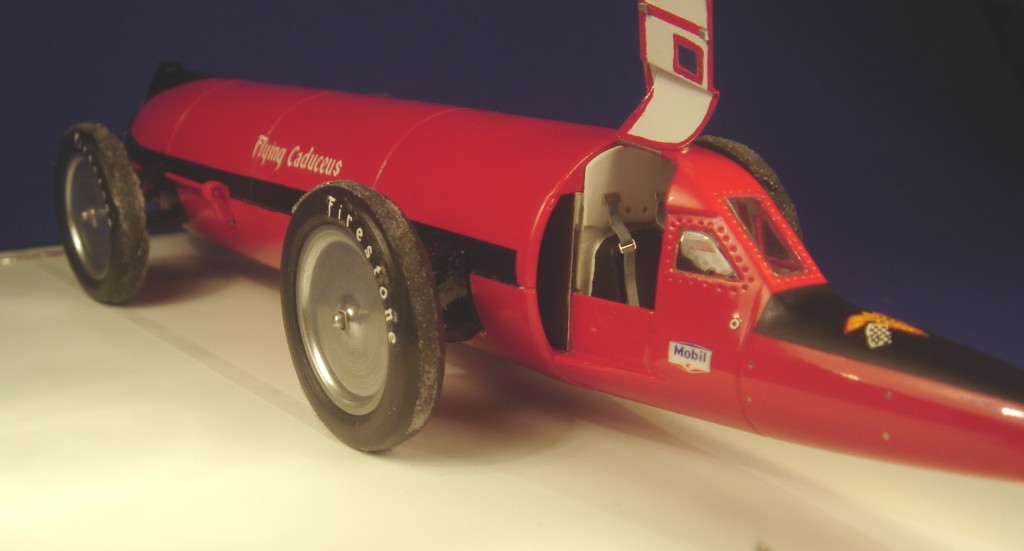
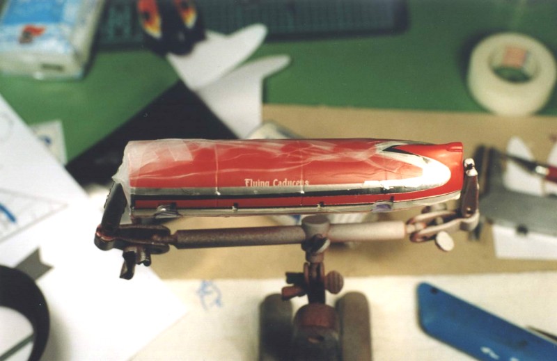
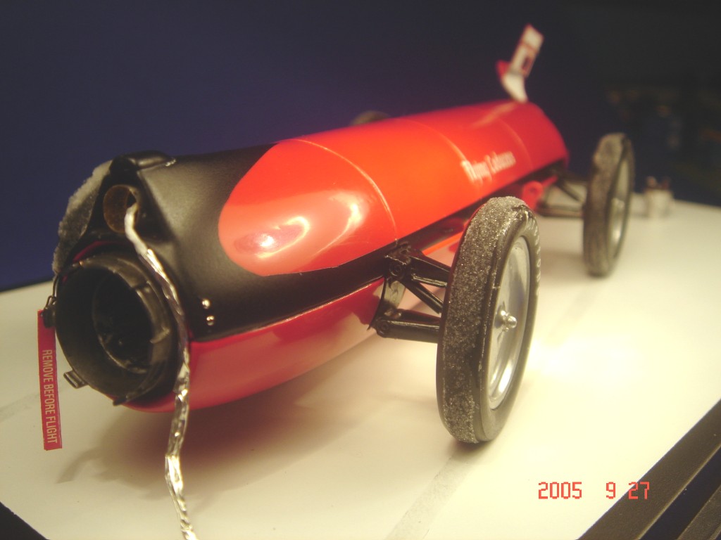
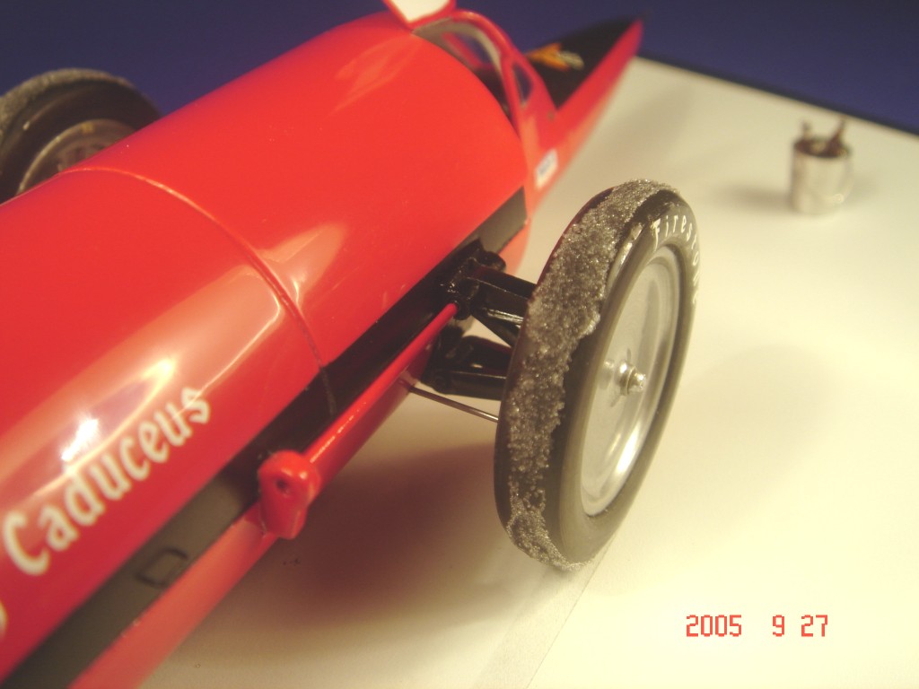
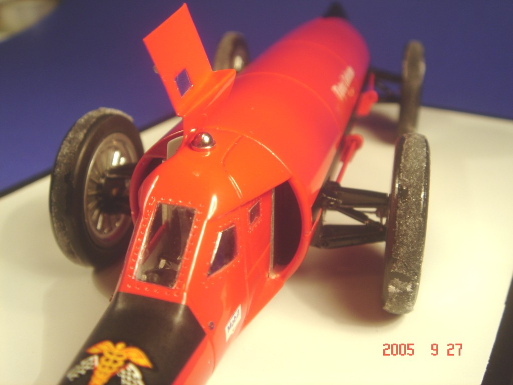
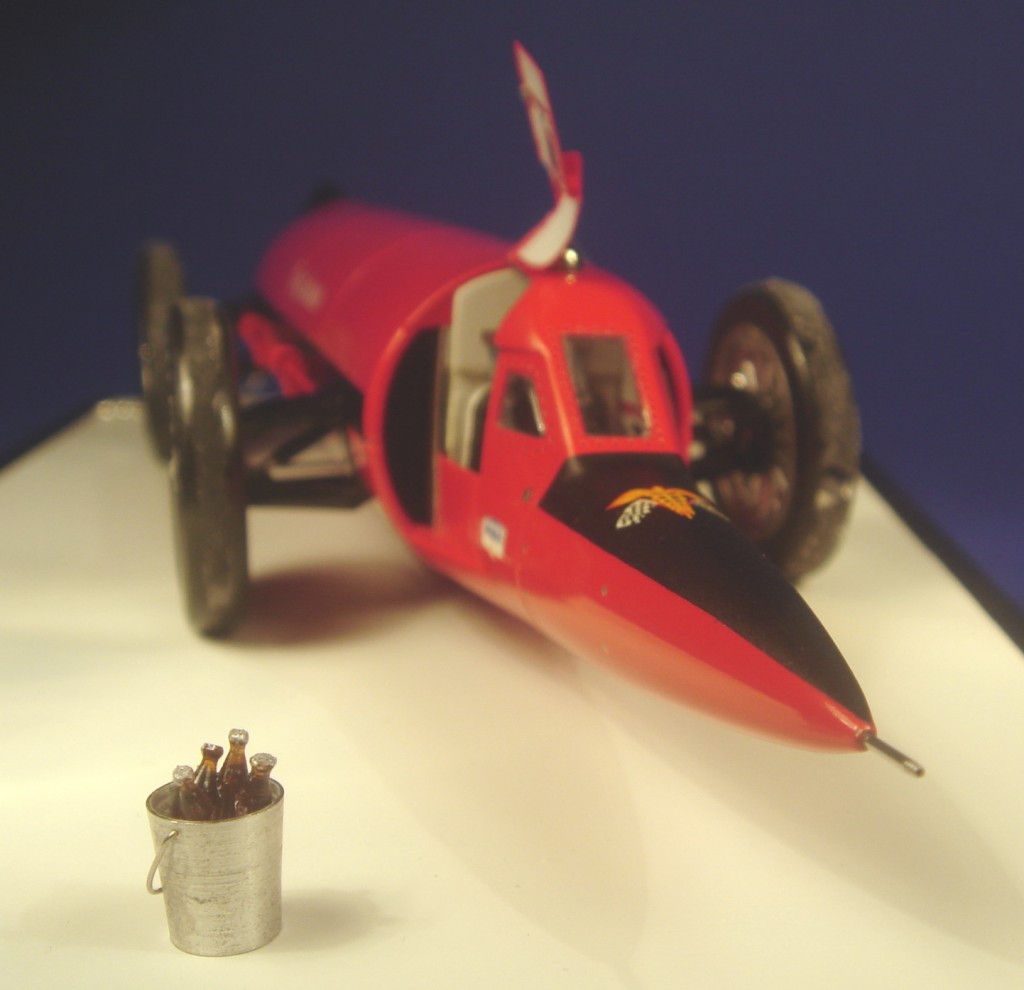
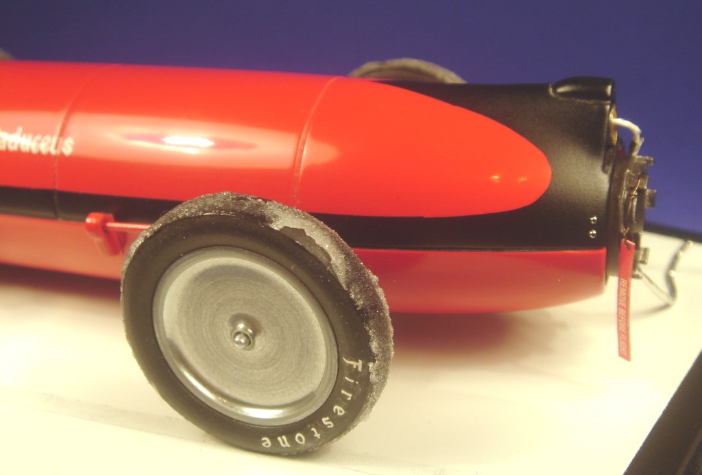
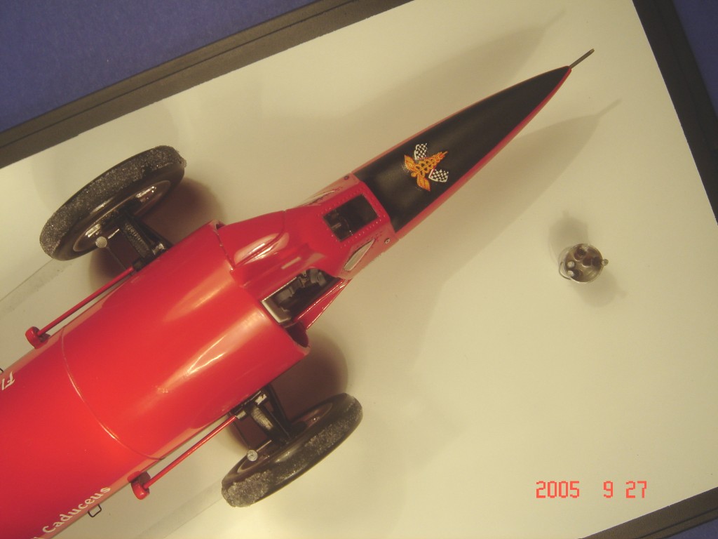
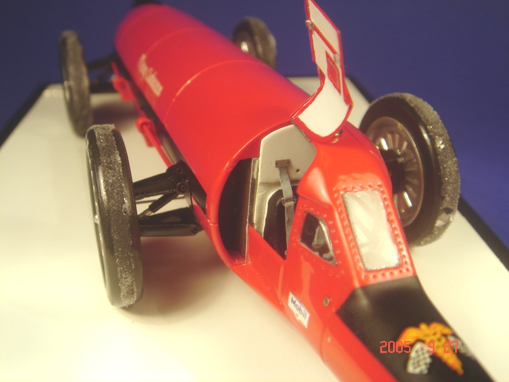
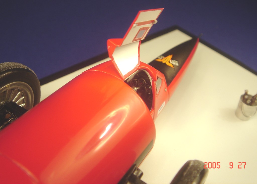
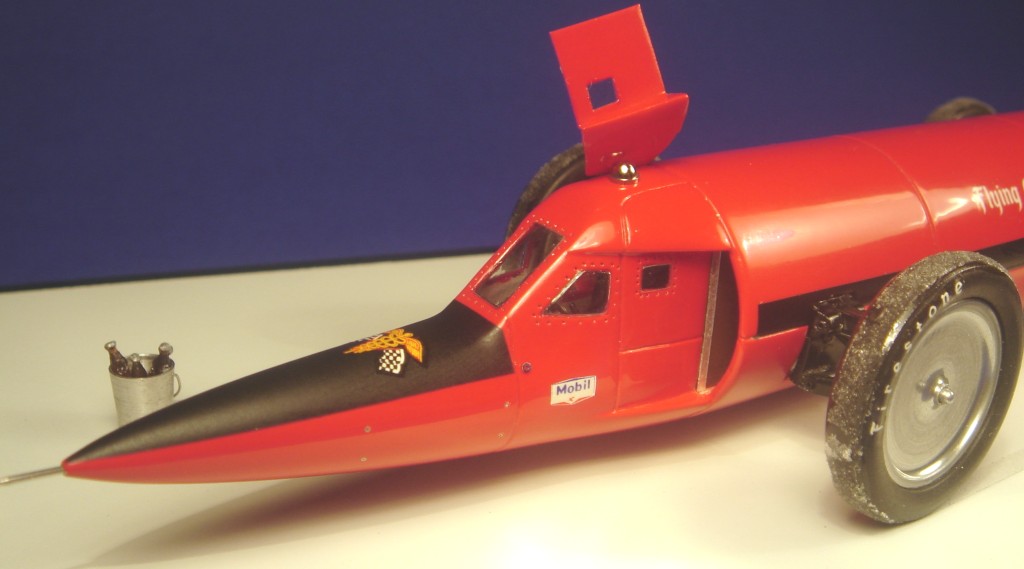
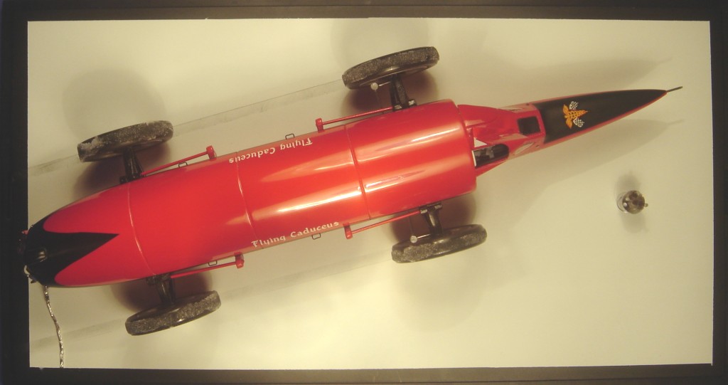
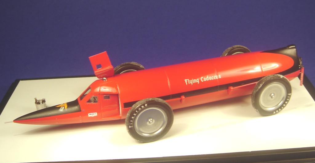
Just like the development of the aircraft engines during WWI had led to a surplus of well developped and powerfull internal combustion engines after the war, WWII had given birth to the jet engine, and by the mid 50’s, the second generation of these jet engines were becoming available through surplus dealers. Dr. Nathan Ostich, L-A physician and LSR enthusiast grabbed the opportunity, and took the speed record scene one step further. The "doc" commissionned the first jet propelled LSR-contender, and made the front-page news (well, in specialized racing magazines anyway) even before he had taken his red rocket to the salts. Aptly named "Flying Caduceus", after the medics’ profession symbol, a serpent winding around a staff, the car sure looked like it would do the job. The huge tires had been especially developed by Firestone, as were he billet aluminium wheels. Despite the encouraging outset, the doctor encountered many problems during the first season, and the best speed he could record with the early configuration "Flying Caduceus" was a disappointing 324 mph and had tremendous stability problems when running at speed. For the 1963 season the car was updated with a stabilizing vertical fin, and fairings over the suspensions and steering mechanism, but still to no avail. It never went faster than 331 mph.
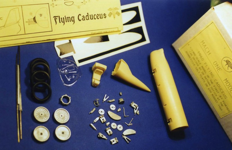
The kit Mach One Models produce both versions of the FC. I chose to build this very attractive replica of the 1960 Flying Caduceus. As with all of their models, this simple, yet beautifully engineered and manufactured kit is a joy to build. It helps if you are familiar with multi-medium kits, combining resin and cast metal parts, but you don’t have to be an expert to turn it into a nice replica..
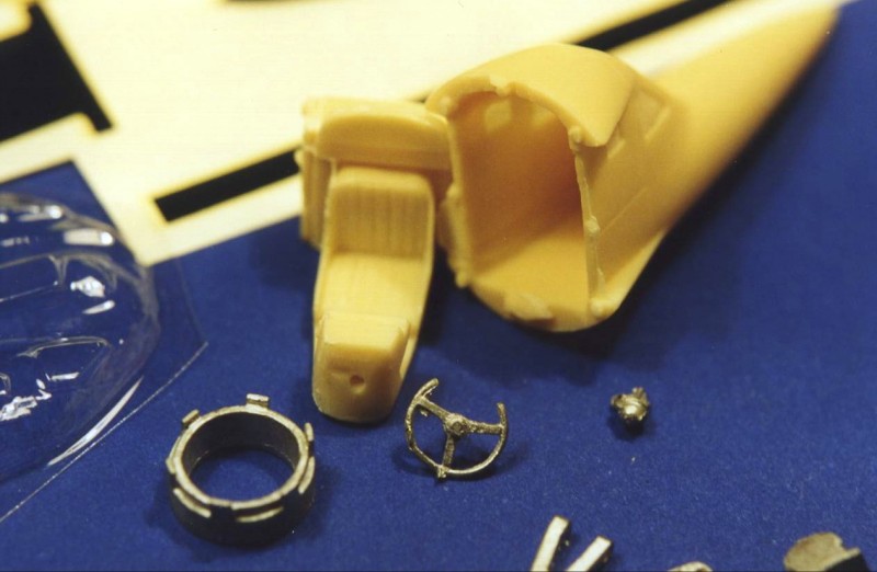
The main parts like cockpit/nose cone, fuselage, cockpit interior are resin. All the other parts are white metal, with the inclusion of copper axle rods and aluminium axle tubes, plus fine wire, rubber tyres, decals and vac-formed windows. No p-e parts are inlcuded in this kit. The resin castings are very smooth, with no air-bubbles, and there is very little flash to the cast metal parts.
Preparation, Modifications and some f-words
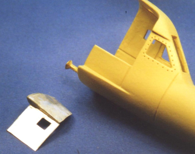
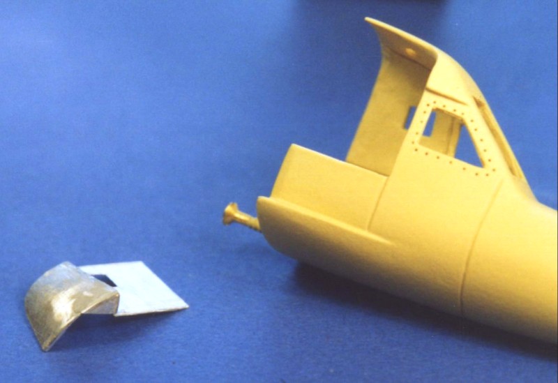
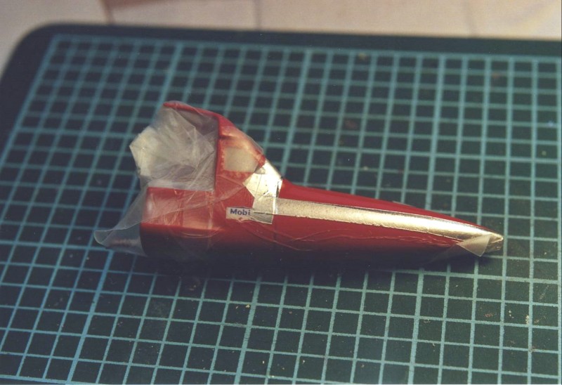
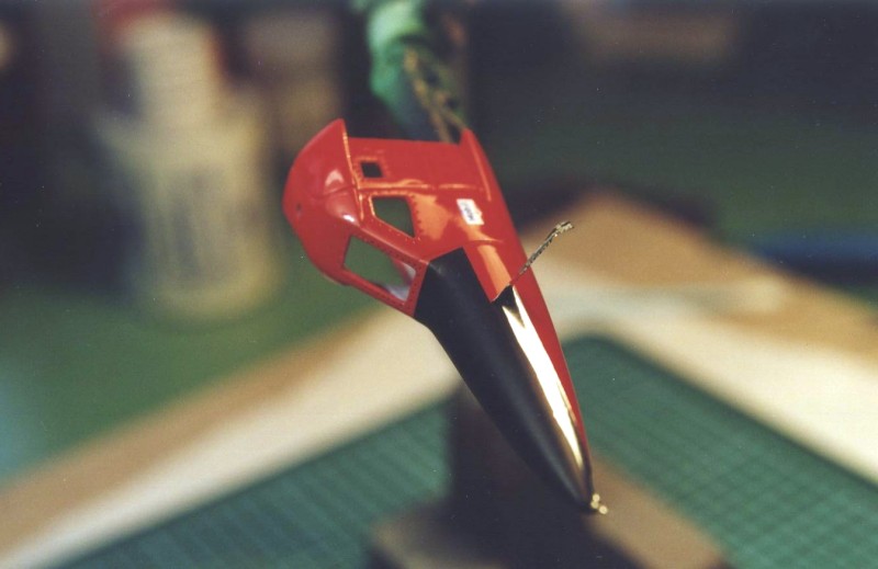
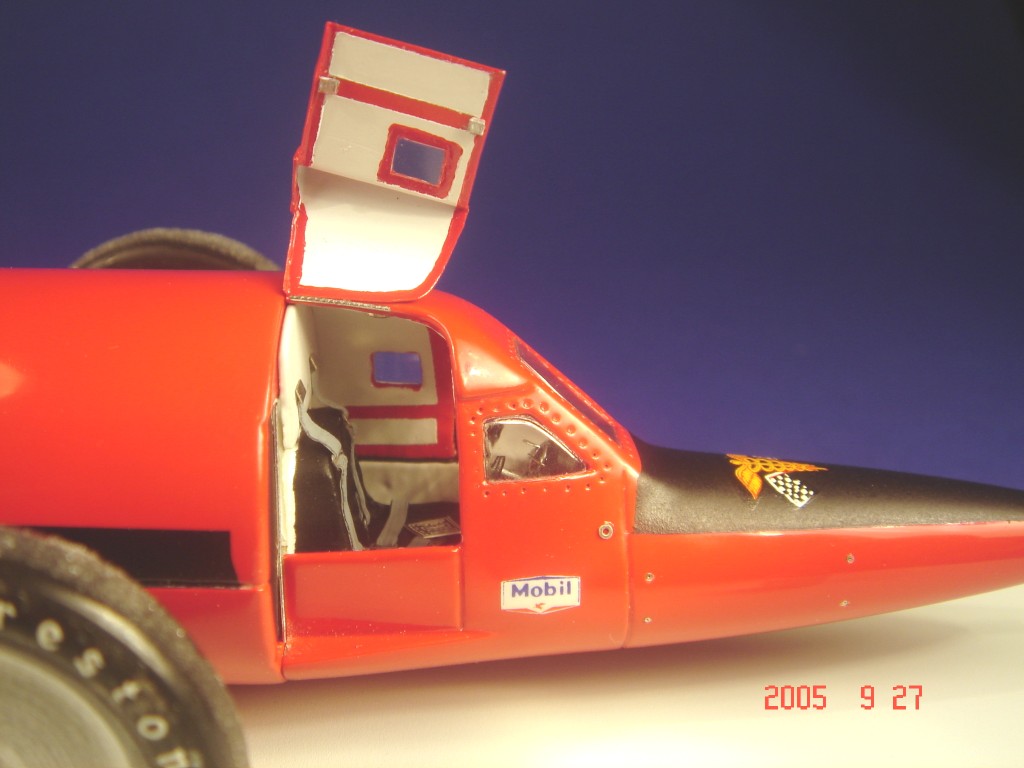
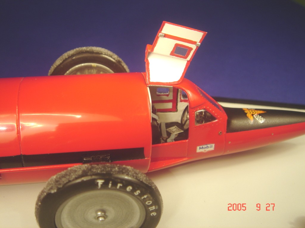
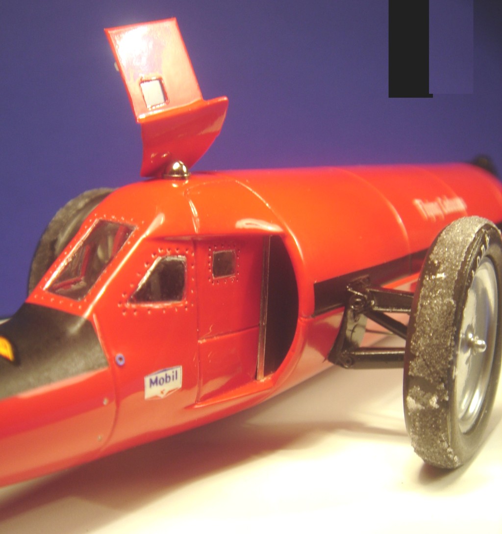
As I wanted to open one of the doors, I made a new door using aluminium foil (from a disposable oven pan). Due to the rather complex shape of the area, there was a lot of fiddling and f-words involved, but eventually it turned out fine. After painting this new door, I felt comfortable enough to cut out the original door, and rework the door sill and jambs.
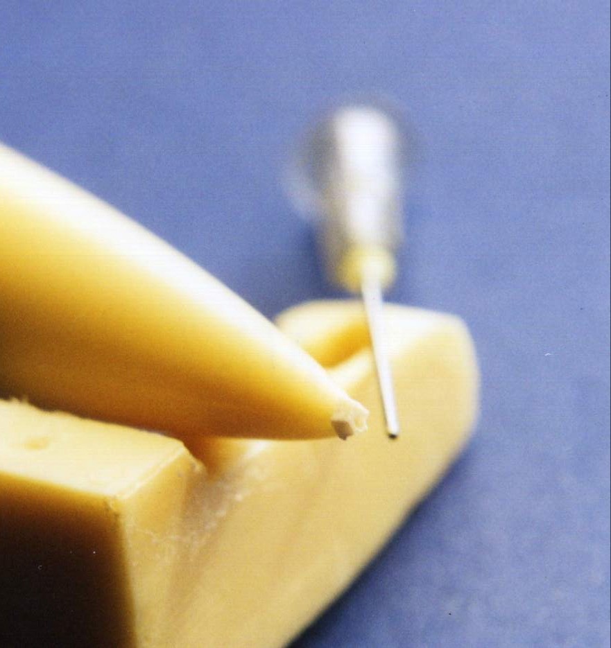
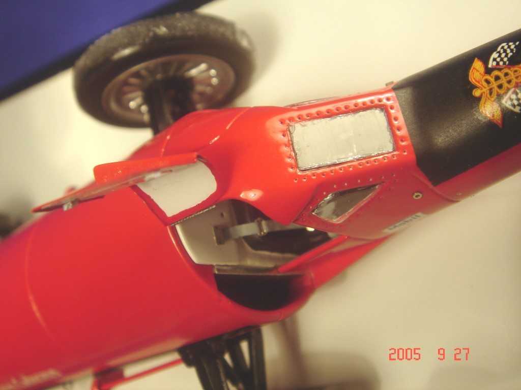
The windows on the real thing were held in place with many small rivets, which were very prominent from the outside. No turned metal rivet whatsoever would be able to reproduce these accurately, so I just drilled 0,3 mm holes to represent them. I think they still look too big on the finished model, but how do you make 0,1 mm rivets?
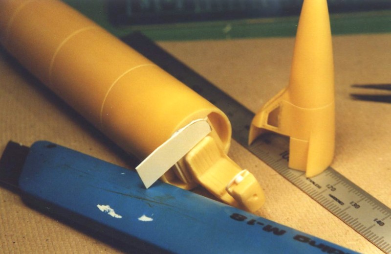
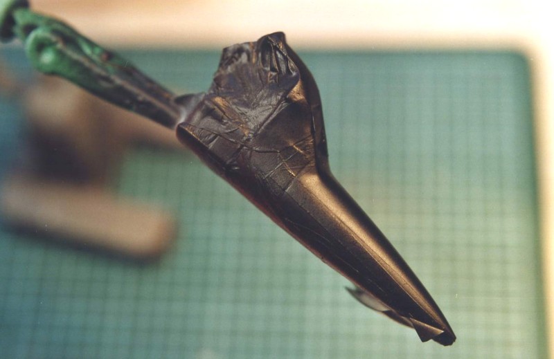
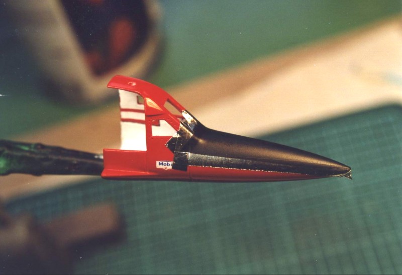
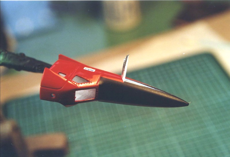
I also milled the business end of the fuselage about an inch deep, so that I could reproduce the rear end intestins of the J47 jet engine. A piece of plastic tubing was detailed with plastic strips, and I added the fan from an old aircraft kit. Good pictures of the jet engine can be found in the Squadron-Signal Walk-Around series on the F-86 Sabre, which used the same type of jet engine. But you don’t really need to replicate a true J47 ; just make it look like an engine nozzle.
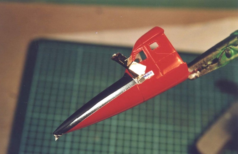
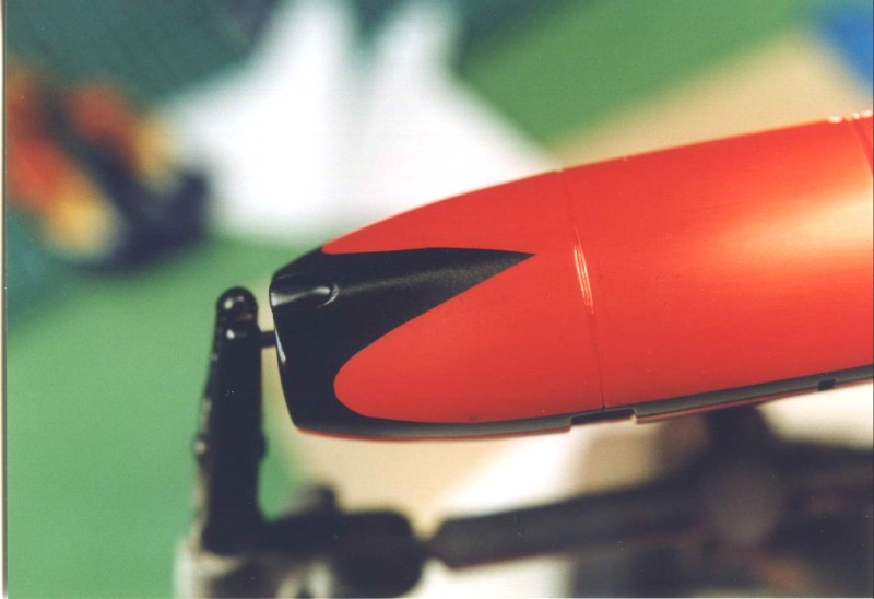
Take special care to adjust the interior and the nose cone to each other, and to the body. The separation line between the nose and the body should be very narrow, like a panel line indeed.
Instead of using the kit supplied brake chute housing (showing the chute in it’s stowed position) I used a piece of steel tubing (from an old telescoping radio antenna).
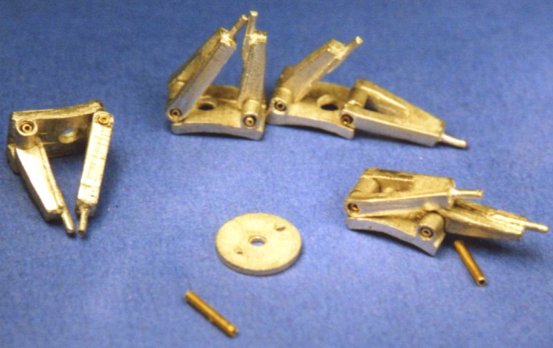
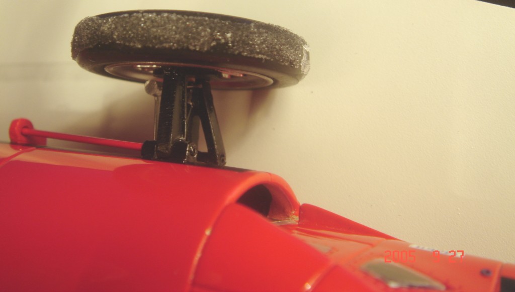
The one “big” error with the kit is that the wheels are meant to be fixed to axles that run right through the car’s body. With the double wishbone suspensions (front and rear), the car will look like a four-wheel drive formula car, whereas the actual car had no axles in such. On the pictures in the various reference books you can clearly see that between the wheels and the body, there are just the wishbones (and shock-absorbers…), no axles. I guess that MOM have included these axles for rigidity purposes, and for ease of assembly and alignment of the model’s suspension. In fact, the resin body plus all the ancilliaries put quite some weight on the model’s wishbones, and there is a real risk of “sagging” if you leave the axles off the model.
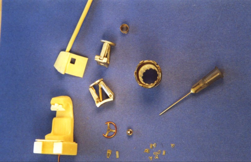
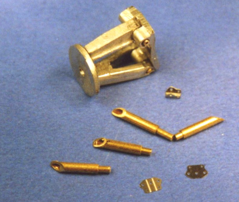
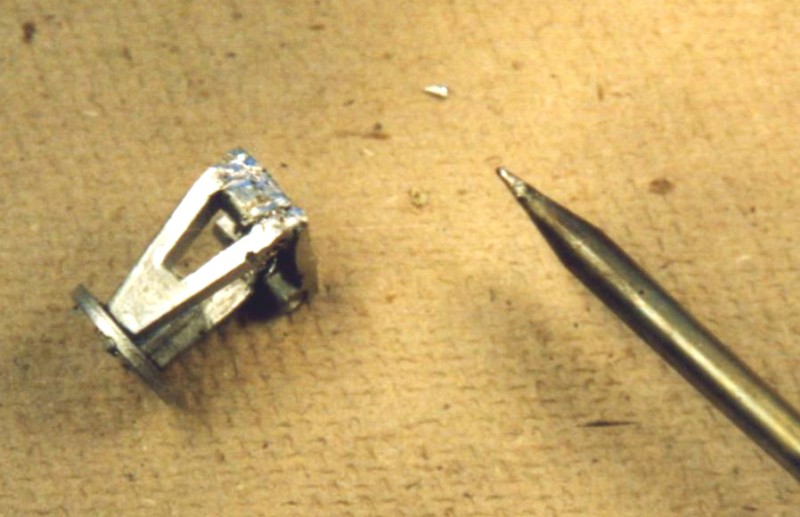
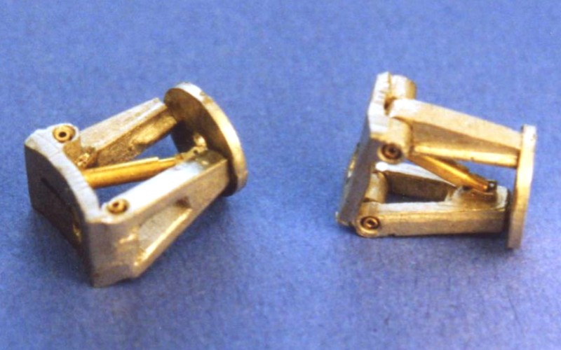
Nevertheless, I took my chances, and modified the kit parts so that the car looks more correct : I modified the wishbones and their fixation point, so that they could actually swing up- and downward. Then I added the brake-disks and dry-assembled the model using the axles provided in the kit ; setting the correct ride-height and aligning the suspensions is very easy this way. I then temporarily fixed the wishbones in their correct position using c-a glue, removed them from the body, and soldered the suspension-assemblies together. Then I filled the axle holes in the « base plates », added shock-absorbers made from telescoping brass tubes with photo-etched « suspension pick up points » (made by Superior, Japan), and painted the whole assembly semi gloss black using Tamiya spraycans.
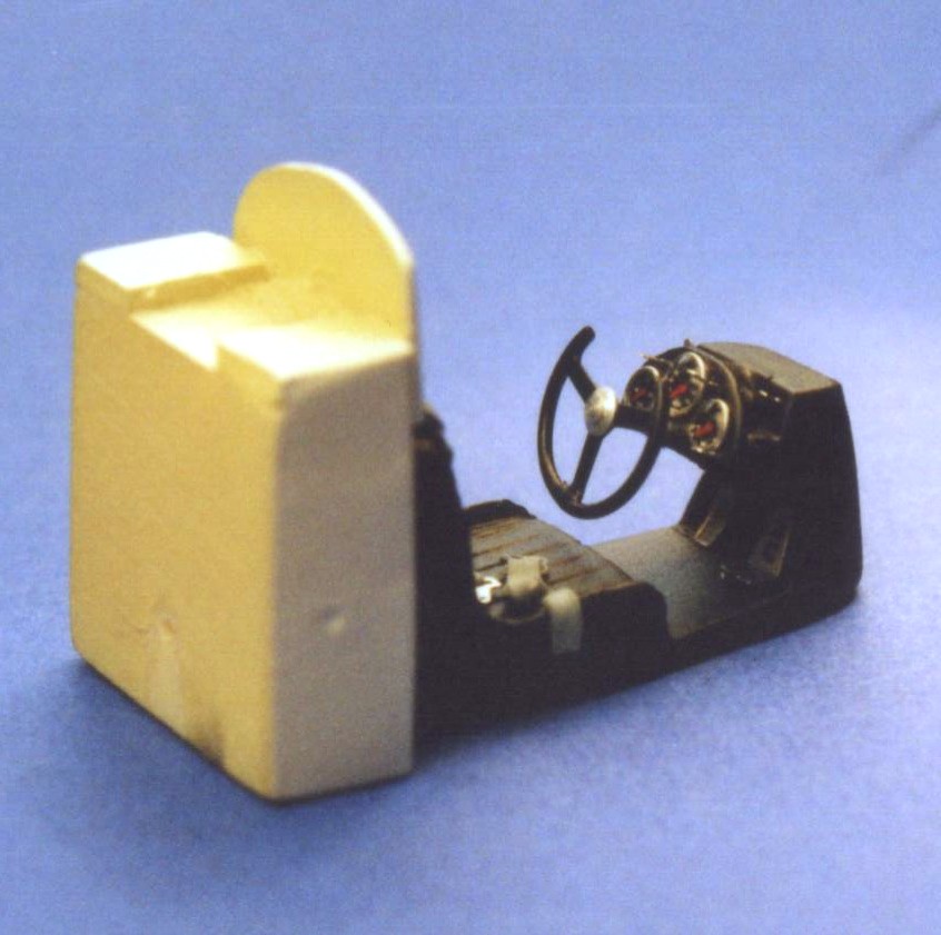
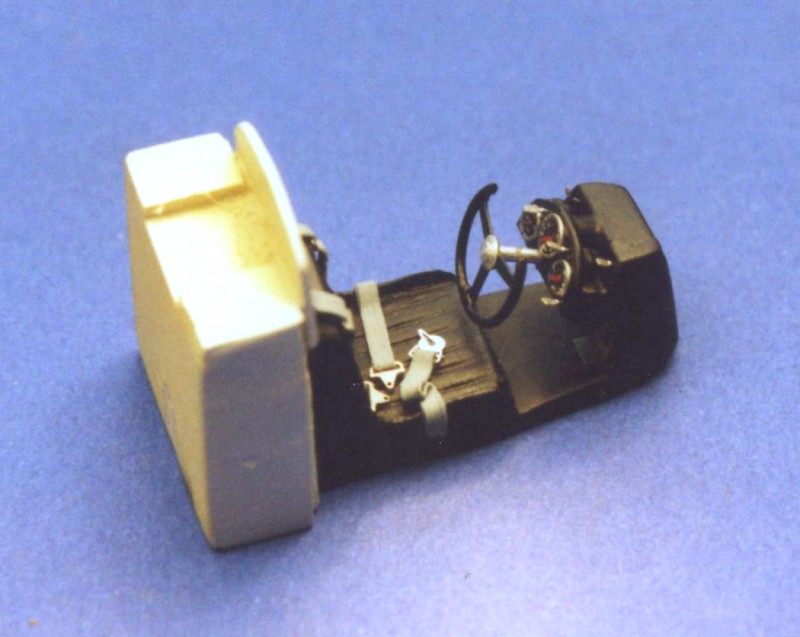
The actual instrument faces are Virages (France) decals,
with bezels made from solder wire and clear 5-minute-epoxy lenses. Finally I
added a few switches, made from solder wire, pressed flat with a pair of good
flat pliers, and 2 floor pedals from the excellent FPM p-e set. The pedals
are guesswork of my own.
Painting
Decals, and many f-words I applied the decals using a lot of Solvaset, and still had a hard time with them. There are not many decals, but in my case they got me into some trouble : They had yellowed quite badly, a problem that can easily be cured by putting the decals in sunlight or daylight. The decal film will become translucent and clear again under the influence of the UV rays of the sun. When I put them into the water to make them slide off their backing paper though, I noticed that a yellowish, jelly-like film had formed all over the backing paper ; it looked like the "glue" had turned foul, and even the decals themselves had their sticky side covered in it. I decided that I could still scrub them off the model if it didn’t work, so I applied them nevertheless. They finally stuck to the surface of the model, but it was hard work, involving many "f-words" (again), and the result is not 100% satisfactory.
When I corresponded with Mach-One-Models on this subject, they told me that the decals can still be used, even when this problem occurs. You have to soak the decals thoroughly, until they come off the backing paper. Then you have to pick up the decal with a new piece of backing paper (from a different set of decals), and slide it onto the model. I found that it is even better to turn the decal over under water and brush the back of the decal clean of the yellowish gel that the glue has turned into. It’s only then that you turn the decal over again, and, still under water, slide it onto a piece of backing paper. After this procedure it should work like most other decals. It’s pretty tedious. As MOM confirmed, there has only ever been one batch of decals produced for this kit, but apparently they do not all present the same problem. Indeed Wayne Moyer in his test-build published in Four Small Weel magazine, 09-2005 edition, does not mention trouble with decals. Maybe I’ve just been unlucky with mine.
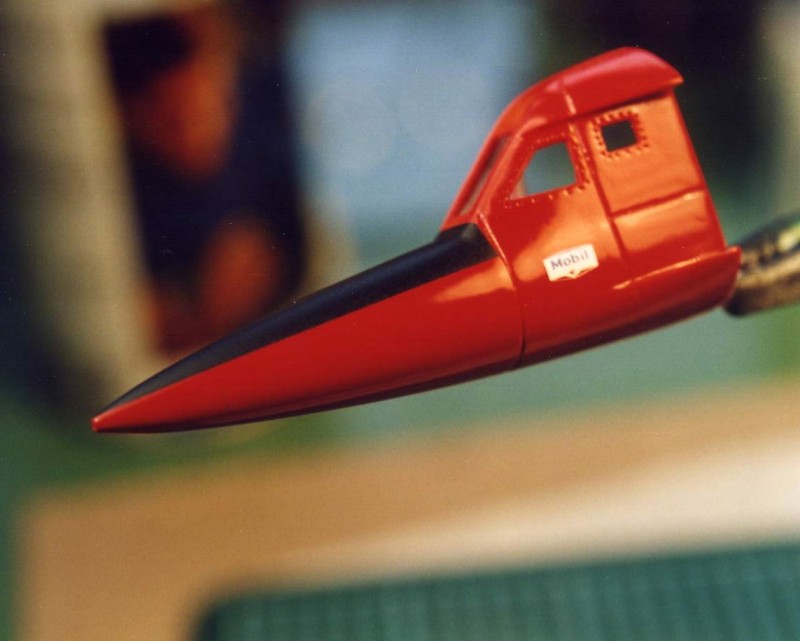
From the decals on the doors of the car, the model must represent FC as it first appeared on the salt on august 6th. I’m not sure wether it did run at all in that configuration; all the pictures that were taken subsequently to this first roll-out on the salt show it to wear additional sponsors logos on the doors, but the decal sheet only includes the champion stickers. I went through my spare decals and for most of the other logos needed I could not find a match, so I only put on the "Champion" decals from the kit’s sheet.
I subsequently applied four coats of clear gloss (3 light, one heavier) on the body parts, and after several weeks of drying (and dedicating time to other models), the body was sanded using increasingly finer polishing cloths.
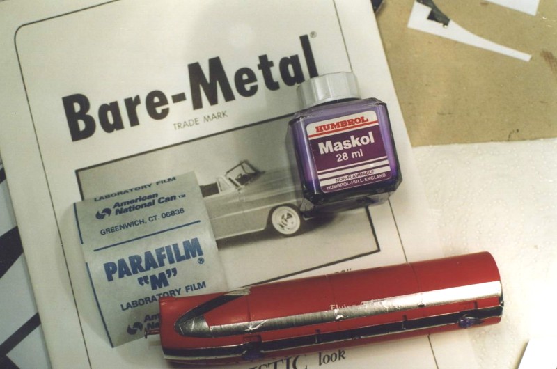
I didn’t want to use the black sections from the decal sheet. First because of the trouble described above, and second because masking and painting is actually easier, faster and gives better results. So, after sanding the body, I masked it using BMF and Parafilm M, a technique described more in detail in the article "How to apply a multi colour paintjob" here on amazing43.com. It’s very easy and fast to mask and paint that way.
Pictures of the real car suggested that the black paint was semi-gloss, which would be well suited for the anti-glare paint on the nose as well. I applied 3 very light coats of semi-gloss black(generic "hobby" spraycan), with only 5 minutes waiting in between. The paint-masks are pulled off gently before the color has dried (about 5 minutes after the last coat has been applied).
More detailing and painting
I didn’t use all of the kit supplied windows. The front screen, and the tiny windows in the doors were replaced with clear plastic, measurements being taken with a caliper. The front screen looks quite marred with glue on the pictures, but the real thing is looks less messy. I used thin "rhodoid glue" by Provence Moulage (also available from the Tron range), and produced the mess while applying it with a small pointed brush. This technique would have worked fine for windows which are glued into a recessed line ; capillary action will draw the glue into the gap between the window and the body. On the FC tiny droplets of c-a glue would have worked better I think.
I drilled a hole through each of the four tyres, and into the rims – through these the model would be fixed to the base with the use of screws. The metal part of the exhaust nozzle was dipped in a metal burnishing chemical, then polished using a brass wire brush ; the plastic part was painted matte black and drybrushed (inside) with different shades of silver and steel.
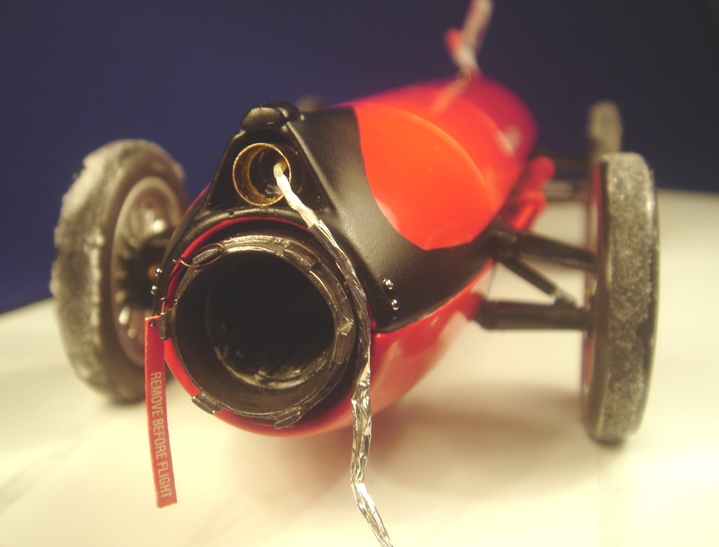
Final assembly and presentation I glued the interior onto the main body, and hooded it with the nose cone / cockpit part, using quick setting c-a glue. The cast metal half dome that sits on top of the cockpit was replaced by Renaissance "turning lights" (24th scale) which is exactly the correct size and shape.
The suspensions, which I had wisely marked and numbered, were glued to the body with 5-minute epoxy (which you have to cure for 24 hours !). Then the wheels could be glued to the brake disks/wheel bearings. You will have to make your own axle stubs if you chose to modify the suspensions like I did. Alignment of the wheels is checked and ensured with the use of a jig.
The brake-chute line, partly wrapped in heat-protective foil (bare metal foil) was added at the rear. The salt on the tyres, this time, is "c-a glue filler", as I couldn’t find the "artificial snow" which I used on the Wingfoot Express II. I strongly advise against using baking soda to replicate salt (or snow in a diorama), as soda has a tendency to attract moisture, and to change its consistency and colour over the time. Although the moisture problem can be avoided by using the c-a type glue, I doubt that c-a will also prevent the yellowing.
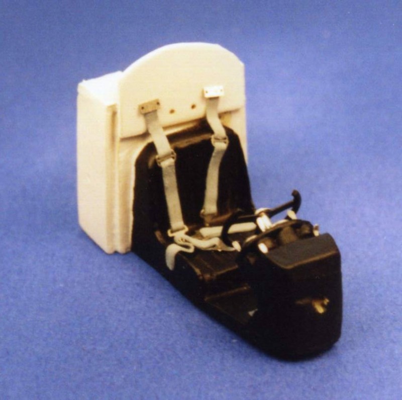
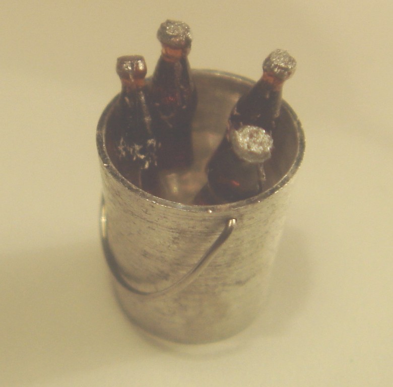
The turned aluminium bucket and the Coke bottles are by Tron. The handle of the bucket was made from very fine solder. The iced water in the bucket is a piece of clear plastic. The bottles were cut at an angle, then glued to the plastic disc. The manual/checklist on the drivers seat is from a Verlinden military accessory sheet.
In a final attempt to overdo things I added four handles to the engine covers, and two rivets each side of the fuselage, right at the rear end of the body. The "remove before flight flag" is from Verlinden. I also wanted to add quick release fasteners to the engine covers, but could not locate more than 4 accurate ones in my p-e details box, but you need 8 to do the job. Anyway, they can hardly be seen on the real car, and would probably have looked overdone on the model.
Conclusions What was intended to be a quick and « out of the box » model, turned out to be (yet again) a long term project. This was a result more of my decision to add and modify some of the kit parts than of the quality of the kit. Apart from the decals, it is reasonably easy to build the kit into a nice replica of this LSR landmark. Check your decals before starting to apply them (use a piece of the backing paper to do the check), and follow my advice on how to apply the decals if your’s present the same problem as mine, and you should be able to build your FC without any major trouble.
Well done Mach-One-Models !
Now what’s next on the workbench… Maybe the Autolite Special ? Should be great fun masking and spraying the body in 4 or 5 different colors, and opening up the cockpit section…
Main references “Bonneville Salt Flats“, by Louise-Ann Noeth “One second from Eternity: The history of the LSR” (video/DVD); very interesting footage of FC; the quality of the sound and of the images is somewhat poor on my copy though “Land Speed Record”, Cyril Posthumus & David Tremayne
Additional references - "100 years of the World’s Land Speed Record 1898-1998; Part 2 The second half century", Ferdinand C.W. Käsmann - "The Land Speed Record" Shire Album N° 263, David Tremayne - "The fastest Men on Earth; 100 years of the Land Speed Record"(1), Peter J.R. Holthusen - "The Land Speed Record 1947-1997 as chronicled in the UK Motoring Press", Transport Source Books - "Fast Facts", The Speed Record Club Quarterly Newsletter, N° 20 - "Walk Around: F-86 Sabre" by Squadron Signal Publications (has pictures of the J47 jet engine) - "Vitesse Illimitée; L’histoire du record absolu de vitesse de 1898 à nos jours", William Huon
(1) contains some rare and very interesting color pictures of different LSR cars, but some reviewers suggested that the accuracy of the text is questionable
Special tools/materials used - Magnetic Gluing Jig, NWSL (via Micro Mark) - Bare Metal Foil (BMF) - Parafilm-M, strechable medical film by 3M - Plastruct plastic tubes and strips - Photo-etched "suspension pick up points" (made by Superior, Japan) - Lead foil (from a good, old bottle of whine; most younger whines don’t have lead foil any more, as it has been banned for health reasons; lead foil is also available from Verlinden Productions as an accessory for military modelling) - Photo-etched seat belt buckles (from a set of generic p-e detail parts by FPM, Germany) - Punch&Die set (by Rai-Ro (Germany) or Waldron (USA)) - Renaissance turned aluminium “turning lights” (24th scale; ref. # CLI) - ScaleMotorsports ref. SKU8117 p-e details - Tron bucket and Coke bottles SP.94 and SP.87 - "Remove before flight" flags (ref. 578) by Verlinden/VLS |